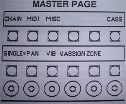
Although the PAGE MODIFIER Section of the Matrix-12's front panel has been mentioned several times so far in the manual, we'd like to summarize its functions and operation.

Primary Page Selection
-
SINGLE PATCH Pages
Pressing the button to the immediate left of any SINGLE PATCH Page name (printed on the front panel in White lettering) will select the Primary Page for that function and display its current status in the PAGE MODIFIER Section. The LED next to its switch will light and the windows in PAGE MODIFIER will then do one of three things:
1. If VCO1, VCO2, FM/LAG or VCF/VCA is selected, the PAGE MODIFIER will display the available parameters for that Page in the Upper Display along with their current settings in the Lower Display.
2. If TRACK X, ENV X, LFO X or RAMP X is selected, the PAGE MODIFIER will prompt you to select which one (that's what the "X" is for). For added programming speed, pressing the button for any of these Pages a second time calls up the last one you selected:
As an example, suppose you were editing LFO 4, switched to VCO1 and then wanted to go back to LFO 4. Pressing LFO X just once will display:
SELECT LFO FROM 1 TO 5
Pressing the LFO X button again will immediately recall LFO 4 for you. Or you can press button #4 in the X SELECT section to select LFO 4.
3. If NAME is selected, PAGE MODIFIER will display NAME and MODULATION ROUTINGS. You may then select either one of these two Sub-Pages to examine or edit. More on these later.
Primary Page Selection
-
MULTI PATCH Pages
Pressing the button to the immediate left of any MULTI PATCH Page name (printed on the front panel in Grey lettering) will select the Primary Page for that function and display its current status in the PAGE MODIFIER Section. The LED next to its switch will light and the windows in PAGE MODIFIER will then do one of three things:
1. If TRANS, PAN, VASSIGN, VOLUME, VIB or DETUNE is selected, the PAGE MODIFIER will display the available parameters for that Page in the Upper Display along with their current settings in the Lower Display. The VOICES 1-6/VOICES 7-12 select switch LED will be lit showing you that you are able to switch between Voice Banks.
2. If ZONE X is selected, the PAGE MODIFIER will prompt you to select which one:
SELECT ZONE FROM 1 TO 6
For added programming speed, pressing the button for this Page a second time calls up the last ZONE you selected.
3. If NAME is selected, PAGE MODIFIER will display the MULTI Patch's name for you to examine or change.
Primary Page Selection
-
MASTER PAGE Sub-Pages
Pressing the button beneath the name of any MASTER PAGE Sub-Page displayed on the PAGE MODIFIER windows will select the Primary Page for that function and display its current status in the PAGE MODIFIER Section.
PAGE MODIFIER Displays
Once you have selected a Page to work with, notice what happens with the SWITCH MODE lights in the PAGE MODIFIER section. Depending on which Primary Page you have selected, these LEDs will inform you as to what kind of operation the six switches directly beneath the window are able to perform.
Upper Display SWITCH MODEs will either be MODULATION PAGE SELECTor ON/OFF status.
If MODULATION PAGE SELECT is lit, this is telling you that the parameters displayed are able to be modulated by any one or several (up to six) of the Matrix-12's 27 Sources of Modulation. Pressing any one of these switches will select that parameter to be modulated. In other words, pressing a switch beneath a certain parameter name on the display selects that parameter to be a Modulation Destination.
In some instances you will notice that one or more of the available parameters will not be able to be modulated and their switches will not be active in this mode. Some examples of these would be VCO 1 and VCO 2 DETUNE and the five POINT values of the TRACK X Generator.
If On/OFF is lit, the parameters displayed are able to be turned ON and will be underlined, or OFF and will be de-underlined.
Lower Display SWITCH Modes can either be VALUE X or ON/OFF status:
If VALUE X is lit, the Amount values of the parameters displayed in the Upper window can be selected by pressing the button beneath the number displayed.
If ON/OFF is lit, the parameters displayed are able to be turned ON and will be underlined, or OFF and will be de-underlined by pressing the button beneath the parameter name in the window.
You will notice that one LED for each display will be lit for all Pages except for TRACK X, RAMP X and NAME.
TRACK X and RAMP X will not have either LED lit for the Upper Display switches because the displays for these Pages simply list the available "fixed" parameters - along with their corresponding Amounts in the Lower Display - and are never modulated.
NAME will also not have either LED lit for the Upper Display switches. This is because the switches directly beneath NAME and MODULATION ROUTINGS are used to select these two additional Sub-Pages.
Sub-Pages Selection
All Primary Pages in this section, except for TRACK X and NAME, have more parameters than can be displayed in the Primary Page windows. Pressing the PAGE 2 switch displays for you the additional parameters that can be used in programming the selected Page.
You will notice that all PAGE 2 functions have SWITCH MODES of ON/OFF. All Primary Pages have MODULATION SOURCE SELECT (for those with possible Destination parameters) and VALUE X SWITCH MODES. This design keeps Page operation consistent.